EPLAN.HOUSE
1/10*l0 - also suitable for this case? Is it necessary to bend the rebar into
Is it at least Lan and 1/10*l0? the lower zone?
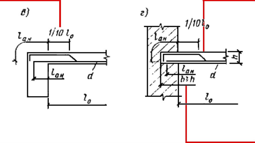
And if the height of the slab is greater than the thickness of the wall.
Fig. 104. Continuous reinforcement of monolithic slabs with individual rods (knitted reinforcement).
c - edge support - reinforced concrete beam; d - the same, brick wall; 1 - bends; 2 - span reinforcement; 3 - additional support rebar (installed if the dowels are not enough)
Why is here 1/4 l0, but in Fig. 104b 1/10*l0?
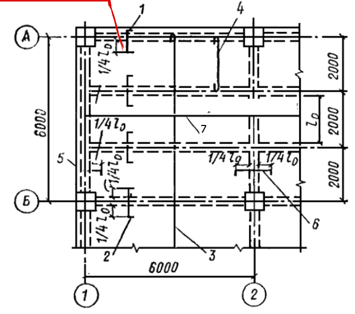
1. Is l₀/10 suitable for Fig. 104b?
I asked a question at one time and came to a clear conclusion - there is an error in the drawing. There is a clear rule: when pinched, the upper rebar should fill 1/4 of the span, and when hinged (simply supported), 1/10. This is explained by the fact that when restrained (pinched), the upper reinforcement is stretched (this is how the bending moment works) and the stretched area must be reinforced. And with a hinge bearing the moment is equal to zero, no stretching, but the constructive rule comes into force, and we still reinforce a small area at the support. The fact is that the ideal hinge, which fully allows for an unobstructed turn, we can not perform in the structures - the slab a little, but pinched, and in its upper support area there are minor, but still stress, there may be cracks, and so the slab we reinforce, but only on the length of 1/10 of the span.
2. Do I have to bend the rebar into the lower zone?
No, it doesn't have to. This solution is related to the economy, it is described in item 3.135 with reference to Fig. 104 (in general, I strongly recommend considering all the figures in the manual together with the text that refers to them). Lower rebar is required in the span, but it is not necessary to bring it all to the support - part of the rebar is bent into the upper support area.
3. What if the height of the floor slab is greater than the thickness of the wall?
Generally, the condition for the hinge is that the support is square b = h, then the slab rests securely (does not slip) and turns without crushing.
What heights are basically slabs? Between 60 and 250 mm, right? That is, the depth of the support also has to be between 60 and 250 mm. But here the rule of anchoring the reinforcement still intervenes - we can not get it on the support less than 100 mm, that is, the support we actually have in the case without welding from 100 to 250 mm (there are exceptions, but they are better to avoid).
If the slab rests on the masonry, I doubt that the masonry will be less than 250 mm - then it is no longer a supporting wall. If it is reinforced concrete, then it is possible to go to pinch the slab, and the issue will be resolved.
4. Why is it in Figure 103 L/4 and Figure 104 L/10?
In Fig. 104 there is an error: either there should be L/4, or it should be shown that the slab rests on a hinged beam. In general, if there are doubtful moments and there is no possibility to make sense of them, it is better to take the worst-case scenario (it concerns the use of the current norms).
Nuances in the reinforcement of monolithic slab support units on the wall
Here you can see several types of support units. Let's find out which one is better.
Is this a correct connection between the floor slab and the monolithic wall?
This solution with dowels is used, I do not like it very much in reliability, I'll explain why.
What's the dowel for? The point is, the upper reinforcement of the plate in a rigid assembly needs to be anchored. For this purpose there is a clear solution in the design manual, shown in Figure 105 (there the slab) is rigidly connected to the beam, but in place of the beam may well be a wall).
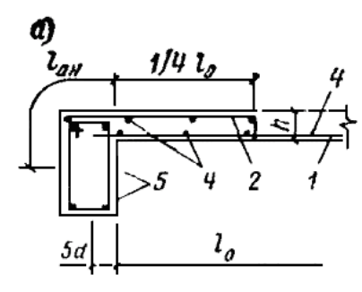
In this solution, the upper rebar covers 1/4 of the span and is tied to the support by the length of the anchor. This is the most reliable solution for slab reinforcement - the reinforcement is anchored in the compressed zone by the amount required.
In this case, it is inconvenient for the builders: usually, the working joint of the pouring is at the top of the wall, and it is inconvenient when the reinforcement of the slab has to be put into the wall (especially if it is large). Some builders lay down L-shaped dowels from the wall in this case (further such a node I will analyze), it is still possible to provide anchoring at the end (so that the bent dowel was shorter, to it welded anchoring elements), but it all complicates the work. For this reason, some designers use U-shaped dowels for anchoring, believing that the dowel will anchor the upper reinforcement in the compressed area of the plate and this will work normally. Is this a good solution? Definitely not, I do not like it very much, because anchoring is carried out in the most stressed zone of the node, and not run into the compressed zone of the wall. The only thing that can improve this solution is to put a U-shaped dowel on the length of the anchorage in the slab so that it does not anchor in the assembly itself (but this is an overrun compared to the assembly in the manual, although installing an additional U-shaped dowel is already an overrun).
Next, follow the upper anchorage of the reinforcement. The upper area must be overlapping, not anchored. There are two options: Either follow the rules and make U-dowels of different sizes so that there is no more than 50% overlap in the section of the slab or use a factor of 2.0 for anchoring (instead of 1.2) and make U-dowels the same (the code allows). After all, in fact, in this node, a dowel is an extension of the upper main reinforcement, installed for its anchoring, so it must connect to it with splicing (and here, by the way, also a violation of regulatory requirements, because the splicing should not be in a stretched section - that's why I do not like neither the solution with U-dowels nor the solution with the L-dowels, as both overflow and violation of standards).
The ideal solution is a continuous top rod, anchored to the length of the anchorage, as it should be, with a bend downwards, while either hitting the wall or not.
But here one more requirement of Eurocode which forces designers to establish U-dowels on ends of slabs appears.
This requirement tells us about the perception of torsional moments that occur at the free edges of the slab (there really need U-shaped dowels - exactly as shown in the picture - covering the reinforcement that runs parallel to the free edge of the slab).
The codes aren't as clear as we'd like them to be. I never recommend a direct violation of regulations. In controversial moments, I advise always to choose the worst option. And of course to think, look for reasons and analyze: when we understand what and why is installed, how it all works, it becomes much easier to construct without errors.