EPLAN.HOUSE
Even though factories of reinforced concrete products produce many finished products, it is still sometimes necessary to make a reinforced concrete slab beam or reinforced concrete lintel yourself. Moreover, when building a house using permanent formwork, you cannot do without it.
Almost everyone has seen construction workers putting some iron into the formwork, and almost everyone knows that this is reinforcement ensuring structural strength. However, only engineers-technologists are good at determining the quantity and diameter of reinforcement or the cross-section of hot-rolled profiles used in reinforced concrete structures as reinforcement. Although used for over a hundred years, concrete structures remain a mystery to most people, or rather, not the structures themselves, but the calculation of reinforced concrete structures. Let us try to lift the veil of mystery over this topic by calculating reinforced concrete beams.
The calculation of any building structure in general and a reinforced concrete beam in particular consists of several stages. First, the geometric dimensions of the beam are determined.
Step 1: Determine the length of the beam
Calculating the actual length of the beam is the easiest. The main thing is that we know the span that the beam should cover in advance, which is already a big deal. The span is the distance between the load-bearing walls for a floor beam or the width of an opening in the wall for a lintel. The span is the calculated length of the beam; the actual length of the beam will, of course, be longer. Since the beam can not hang in the air (I am thinking about it, but no solution has yet been found), so the length of the beam must be longer than the span by the width of the support on the walls.
Furthermore, although all further calculations are based on the calculated rather than actual length of the beam, it is still necessary to determine the natural length of the beam. The width of the supports depends on the strength of the structure material under the beam and the length of the beam; the more potent the structure material under the beam and the smaller the span, the smaller the support width can be. Theoretically, calculate the width of supports, knowing the structure's material under the support can be precisely the same as the beam itself. However, usually, no one does if it is possible to support a beam on the brick, stone, and concrete (concrete) walls to 150-300 mm at a span of 2-10 meters. For hollow brick and cinder block walls, it may be necessary to calculate the width of the support.
For example, let us take the value of the calculated girder length = 4 m.
Step 2: Preliminary determination of beam width and height and concrete class (grade)
These parameters we do not know exactly, but they should be set to have something to count.
If it will be a lintel, it is logical for structural reasons to make a lintel of a width approximately equal to the width of the wall. The width can be anything for floor joists, but it is usually taken at least 10 cm and a multiple of 5 cm (for ease of calculation). The height of the beam is taken for structural or aesthetic reasons. For example, it is logical for masonry to make a lintel height of 1 or 2 brick height, porous block - 1 block height, etc. If the floor joists will be visible after construction, it is also logical to make the height of the joists proportional to the width and length of the joists and the distance between the joists. If the floor beams are concreted simultaneously with the floor slab, the full height of the beam in the calculations will be the visible height of the beam + the height of the monolithic floor slab.
For the example, we take the values of width = 10 cm, height = 20 cm, concrete class B25.
Step 2: Preliminary determination of beam width and height and concrete class (grade
These parameters we do not know exactly, but they should be set to have something to count.
If it will be a lintel, it is logical for structural reasons to make a lintel of a width approximately equal to the width of the wall. The width can be anything for floor joists, but it is usually taken at least 10 cm and a multiple of 5 cm (for ease of calculation). The height of the beam is taken for structural or aesthetic reasons. For example, it is logical for masonry to make a lintel height of 1 or 2 brick height, porous block - 1 block height, etc. If the floor joists will be visible after construction, it is also logical to make the height of the joists proportional to the width and length of the joists and the distance between the joists. If the floor beams are concreted simultaneously with the floor slab, the full height of the beam in the calculations will be the visible height of the beam + the height of the monolithic floor slab.
For the example, we take the values of width = 10 cm, height = 20 cm, concrete class B25.
Step 3: Determine supports
From the point of view of resistivity, whether it is a lintel over a door or window opening or a floor beam does not matter. However, how the walls support the beam is of great importance. From the point of view of building physics, any real support can be considered hinged support around which the beam can conditionally rotate freely or as a rigid support. In other words, a rigid support is called a pinch at the ends of the beam. Why so much attention is given to beam supports will become apparent below.
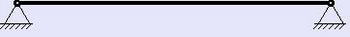
Beam on two hinged supports.
Suppose a reinforced concrete beam is placed in its designed position after fabrication. In that case, the width of the beam resting on the walls is less than 200 mm, the ratio of the beam length to the resting width is more significant than 15/1, and the beam does not include embedded parts for rigid connection to other structural elements. This reinforced concrete beam must be considered as a beam on hinged supports. The following notation is adopted for such a beam:
2. beam with a rigid pinch at the ends.
Suppose a reinforced concrete beam is fabricated directly at the installation site. In that case, such a beam can be considered restrained at the ends only if both the beam and the walls on which the beam rests are concreted simultaneously or if the concreting of the beam includes embedded parts for rigid connection with other structural elements. In all other cases, the beam is treated as lying on two hinged supports. The following notation is used for such a beam:

3. multi-spanning girder
Sometimes it is necessary to calculate a reinforced concrete slab beam that will overlap two or even three rooms at once, a monolithic reinforced concrete slab over several slab beams or a lintel over several adjacent openings in the wall. In such cases, the beam is considered to be multi-span if the supports are articulated. In the case of rigid supports, the number of spans does not matter; since the supports are rigid, each part of the beam can be considered and calculated as a separate beam.
4. Cantilever beam
A beam with one or two ends of which have no supports and are at some distance from the ends of the beam is called a cantilever beam. For example, a floor slab that protrudes a few centimeters beyond the foundation can be considered a cantilevered beam, and a lintel with larger supports than l/5 can also be considered a cantilevered beam and so on.
Step 4: Determine the load on the beam
Loads on a beam can be of many kinds. In terms of structural physics, anything stationary on the beam, nailed, glued, or suspended is a static load. Anything that walks, crawls, runs, rides, or even falls on the beam is all dynamic load. The load can be a concentrated load, e.g., a person standing on a beam or the wheels of a car resting on a beam 3 meters or more in length, which can be conventionally considered a concentrated load. The concentrated load is measured in Newtons (old-fashioned, kilogram-force (kgf)).
However, bricks, ceramic blocks, or any other material lying on the lintel, floor slabs, snow, rain and even wind, earthquake, tsunami, and many other things can be considered distributed loads were acting on the lintel or floor beam. In addition, a distributed load can be uniformly distributed, uniformly and irregularly varying in length, etc. The distributed load is measured in N(kg/m2). However, the distributed load per linear meter is used in the calculations since the construction of bending moment diagrams does not take into account the height or width of the beam but only the length of the beam. It is not difficult to convert square meters into linear meters. If a slab beam is calculated, the distributed load is logically multiplied by the distance between the axes of the slab beams. If the load on the lintel is determined, you can multiply the material density of the structure lying on the lintel by the width and height of the structure.
The more accurately we calculate the loads acting on the beam, the more accurate our calculation will be, and the more reliable the construction will be. Moreover, if everything is more or less straightforward with static loads, they are dynamic because they do not stand still and try to complicate our already tricky calculations.
On the one hand, the design should be calculated for the maximum unfavorable combination of loads; on the other hand, the theory of probability says that the probability of such a combination of loads is minimal and to calculate the design for the maximum unfavorable combination of loads, it means inefficient use of construction materials and human resources.
A house built according to all the rules and capable of withstanding almost anything, including a nuclear strike, no one but a crazy millionaire would buy, too expensive. Therefore, dynamic loads are used with various correction factors that consider the probability of a combination of loads in calculating structures. However, as practice shows, it is impossible to take everything into account. Buildings collapsing during earthquakes, hurricanes, tsunamis, and even heavy snowfalls vividly confirm this. To make life somehow easier not only for design engineers but also for ordinary people, it is customary to calculate the intermediate floors for the distributed load of 400 kg/m2 (without considering the weight of the floor structure). This distributed load takes into account practically all possible combinations of loads on the floor of residential buildings. However, no one forbids to calculate the structures for heavy loads; for example, if the reinforced concrete beams will have a hefty slab, for example, reinforced concrete hollow core slabs will add another 300-330 kg/m2, we will stop at the value of 400 kg/m2. Of course, we could say that we will calculate the beam for a distributed load of 400 kg/m2 with a 1-meter step between the beams, but I would like you to have at least a rough idea of where that figure came from.
Step 5: Determine the maximum bending moment acting on the cross-section of the beam.
Here it all depends on what loads are acting on the beam, what kind of beams support and how many spans; some types of beams, considered in step 2, are statically indeterminate, and although you can calculate it yourself, we will not go into theory, it is easier to use ready-made formulas for the most typical cases.
Example of calculation of a reinforced concrete beam on hinged supports with a distributed load.
The maximum bending moment for a beam resting on two hinged supports, and in our case a slab beam resting on walls with a distributed load, will be in the middle of the beam:
For a span of 4 meters Мmax = (400 · 42) / 8 = 800 кг·м
Step 6: Calculation prerequisites:
Reinforced concrete is a composite material; the strength properties depend on many factors that are difficult to accurately account for in the calculation. In addition. Concrete works well in compression because of its relatively high compressive strength, while reinforcement works well in tension, and in compression, the rebar may bulge. Therefore, the design of a reinforced concrete structure comes down to determining the compressed and tensile zones.
In the tensile zones, reinforcement is installed. In this case, the height of the compressed and stretched zones is not known in advance, and therefore it is not possible to use the usual methods of section selection as for a timber or metal beam.
Calculation on the strength of reinforced concrete structures is performed for normal and inclined to the longitudinal axis sections in the most stressed places (for this purpose, we determined the value of the moment).
Several calculation methods have been developed based on the accumulated experience in the calculation and operation of reinforced concrete structures. One of them, based on the following design assumptions, is given below:
- Tensile strength of concrete is assumed to be zero;
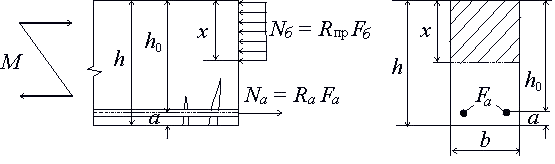
- The concrete resistance to compression is assumed to be uniformly distributed, equal to Rpr (Rb according to the new SNiP);
- the maximum tensile stresses in the reinforcement are equal to the design tensile strength Ra (Rs according to the new SNiP);
- compressive stresses in the stressed and unstressed reinforcement are taken no more than the design resistance to compression Rа (Rsc by the new SNIP);
- it is recommended to use elements of such cross-sections so that calculated by calculation, the relative height of the concrete compressed zone ξ=x/h0 did not exceed its boundary value ξR, at which the limit state of an element comes when stresses in the stretched zone reach rated resistance Rа.
The boundary condition has the form
The formula determines the value ξR:
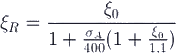
Where
ξo - characteristic of the compressed zone of concrete, determined for heavy concrete and concrete on porous aggregates by the formula:
Apr is taken in MPa; coefficient a = 0.85 for heavy concrete and a = 0.8 for concrete on porous aggregates.
The stress value σA in the reinforcement is taken at 0.002Ea = 400 MPa to be equal for reinforcement classes:
A-I, A-II, A-III, B-I и Вр-1: (Ra - σo);
A-IV, Ат-IV, A-V, At-V, At-VI, B-II, Bp-II и K-7: (Ra + 400 - σ0),
Where
Ra - design resistance of the reinforcement to tension, taking into account the coefficients of working conditions of the reinforcement ma, σo - the value of prestressing of reinforcement, taking into account losses at the tensioning accuracy factor mт < 1.
If in the calculation of bendable elements the coefficient of concrete working conditions is taken into account mб1 = 0,85, then in формулу (6.2) 500 is substituted for 400.
The further calculation we will perform for the beam with conventional (not prestressed) reinforcement, and calculate the section of the reinforcement we will only for the lower part of the beam, in which the tensile stresses, this does not mean that the top of the beam reinforcement (installed for technological reasons) will not, but it will significantly simplify the calculation.
When calculating elements of rectangular cross-section with a single unstressed reinforcement (when the designed reinforcement is installed only in the tensile area), you can use auxiliary Table 1 and formulas:
где
Аo =x/ho(1 - x/2ho) = ξ(1 -0,5ξ) (6.6)
η = (1 - x/2ho) = 1 - 0,5ξ (6.7)
The reinforcement factor μ and the percentage of reinforcement μ-100 (%) is determined by the formulas:
μ = Fa/bho, или μ = ξRпр/Ra (6.8)
Based on the experience of designing the optimal cost of reinforced concrete products is recommended to take:
μ% = 1÷2%, ; ξ = 0,3÷0,4 - для балок (6.10)
μ% = 0,3÷0,6%, ξ = 0,1÷0,15 - для плит перекрытия (6.11)
Table 1. Data for the calculation of bendable elements of rectangular cross-section, reinforced by a single reinforcement (according to the "Manual for the design of concrete and reinforced concrete structures of heavy and light concretes without prestressing of the reinforcement (to SNiP 2.03.01-84)")
| ξ = x/h0 | r0=1/sqrt(A0) | η = zσ/h0 | A0 | ξ = x/h0 | r0=1/sqrt(A0) | η = zσ/h0 | A0 |
| 0,01 | 10 | 0,995 | 0,01 | 0,36 | 1,84 | 0,820 | 0,295 |
| 0,02 | 7,12 | 0,990 | 0,02 | 0,37 | 1,82 | 0,815 | 0,301 |
| 0,03 | 5,82 | 0,985 | 0,03 | 0,38 | 1,8 | 0,810 | 0,309 |
| 0,04 | 5,05 | 0,980 | 0,039 | 0,39 | 1,78 | 0,805 | 0,314 |
| 0,05 | 4,53 | 0,975 | 0,048 | 0,40 | 1,77 | 0,80 | 0,320 |
| 0,06 | 4,15 | 0,970 | 0,058 | 0,41 | 1,75 | 0,795 | 0,326 |
| 0,07 | 3,85 | 0,965 | 0,067 | 0,42 | 1,74 | 0,790 | 0,332 |
| 0,08 | 3,61 | 0,960 | 0,077 | 0,43 | 1,72 | 0,785 | 0,337 |
| 0,09 | 3,41 | 0,955 | 0,085 | 0,44 | 1,71 | 0,780 | 0,343 |
| 0,1 | 3,24 | 0,950 | 0,095 | 0,45 | 1,69 | 0,775 | 0,349 |
| 0,11 | 3,11 | 0,945 | 0,104 | 0,46 | 1,68 | 0,770 | 0,354 |
| 0,12 | 2,98 | 0,940 | 0,113 | 0,47 | 1,67 | 0,765 | 0,359 |
| 0,13 | 2,88 | 0,935 | 0,121 | 0,48 | 1,66 | 0,760 | 0,365 |
| 0,14 | 2,77 | 0,930 | 0,13 | 0,49 | 1,64 | 0,755 | 0,370 |
| 0,15 | 2,68 | 0,925 | 0,139 | 0,50 | 1,63 | 0,750 | 0,375 |
| 0,16 | 2,61 | 0,920 | 0,147 | 0,51 | 1,62 | 0,745 | 0,380 |
| 0,17 | 2,53 | 0,915 | 0,155 | 0,52 | 1,61 | 0,740 | 0,385 |
| 0,18 | 2,47 | 0,910 | 0,164 | 0,53 | 1,60 | 0,735 | 0,390 |
| 0,19 | 2,41 | 0,905 | 0,172 | 0,54 | 1,59 | 0,730 | 0,394 |
| 0,2 | 2,36 | 0,900 | 0,18 | 0,55 | 1,58 | 0,725 | 0,399 |
| 0,21 | 2,31 | 0,895 | 0,188 | 0,56 | 1,57 | 0,720 | 0,403 |
| 0,22 | 2,26 | 0,890 | 0,196 | 0,57 | 1,56 | 0,715 | 0,408 |
| 0,23 | 2,22 | 0,885 | 0,203 | 0,58 | 1,55 | 0,710 | 0,412 |
| 0,24 | 2,18 | 0,880 | 0,211 | 0,59 | 1,54 | 0,705 | 0,416 |
| 0,25 | 2,14 | 0,875 | 0,219 | 0,60 | 1,535 | 0,7 | 0,420 |
| 0,26 | 2,1 | 0,870 | 0,226 | 0,61 | 1,53 | 0,695 | 0,424 |
| 0,27 | 2,07 | 0,865 | 0,236 | 0,62 | 1,525 | 0,690 | 0,428 |
| 0,28 | 2,04 | 0,860 | 0,241 | 0,63 | 1,52 | 0,685 | 0,432 |
| 0,29 | 2,01 | 0,855 | 0,248 | 0,64 | 1,515 | 0,680 | 0,435 |
| 0,30 | 1,98 | 0,850 | 0,255 | 0,65 | 1,51 | 0,675 | 0,439 |
| 0,31 | 1,95 | 0,845 | 0,262 | 0,66 | 1,5 | 0,670 | 0,442 |
| 0,32 | 1,93 | 0,840 | 0,269 | 0,67 | 1,495 | 0,665 | 0,446 |
| 0,33 | 1,9 | 0,835 | 0,275 | 0,68 | 1,49 | 0,660 | 0,449 |
| 0,34 | 1,88 | 0,830 | 0,282 | 0,69 | 1,485 | 0,655 | 0,452 |
| 0,35 | 1,86 | 0,825 | 0,289 | 0,70 | 1,48 | 0,650 | 0,455 |
Step 7: Calculation of rebar cross-section
The dimensions of the reinforced concrete beam and the position of the reinforcement can be set by ourselves, based on technological requirements or other considerations. For example, we decided that the beam will have a height of h = 20 cm and a width b = 10 cm. The distance of the center of the cross-section of the reinforcement from the bottom of the beam is usually taken within the range of 2-3 cm.
Further calculation we will perform at a = 2 cm. Design tensile strength of A-III class reinforcement according to Table 5.8 (СП 52-101-2003 Бетонные и железобетонные конструкции без предварительного напряжения арматуры):
| Armature grades | Calculation values of resistance of reinforcement for limit states of the first group, MPa | ||
| растяжению | сжатию Rsc | ||
| продольной Rs
| поперечной Rsw (хомутов и отогнутых стержней) | ||
| А240 | 215 | 170 | 215 |
| A300 | 270 | 215 | 270 |
| А400 | 355 | 285 | 355 |
| А500 | 435 | 300 | 435 (400) |
| В500 | 415 | 300 | 415 (360) |
| Примечание - Значения в скобках используют только при расчете на кратковременное действие нагрузки. | |||
Ra = 3600 kg/cm2 (355 MPa). It is now common to use new designations for reinforcement classes. Design resistance to compression for the concrete class B25 according to Table 4 Rpr (Rb) = 148 kg/cm2 (14.5 MPa, however for the calculations, we can use an approximate value of 145 kg/cm2, which will give a small margin of safety of about 2%, but not require accurate conversion of MPa in kgf/cm2). Now we have all the data to determine the Ao coefficient. Converting formula (6.4), we obtain:
Аo = M/bh2oRпр = 800/(0,1·0,182·1480000) = 0,1668
We can now find η = 0.907 and ξ = 0.187 from auxiliary table 1. The resulting value of ξ is less than the recommended value for beams (according to formula 6.10). To reduce the cost of the beam, we can reduce both beam width and height so that the resulting value of ξ is within the recommended limits or reduce the concrete grade. To begin with, we will reduce the height of the beam from 20 cm to 15 cm. Then:
Аo = M/bh2oRпр = 800/(0,1·0,132·1480000) = 0,3264
as shown in table 1η = 0,795 и ξ = 0,41
Then according to formula (6.5), the required cross-sectional area of the reinforcement:
Fa = M/ηhoRa = 800/(0.795-0.13-36000000) = 0.0002152 m2 or 2.152 cm2.
Thus, 2 rods with a diameter of 12 mm are sufficient to reinforce our beam. The cross-sectional area of the reinforcement will be 2.26 cm2. It is convenient to select the reinforcement according to Table 2 (see below).
The reinforcement factor of our beam according to formulas (6.8) and (6.9) will be:
μ% = 100·0.41·148/3600 = 1,65 %
This percentage is within the recommended limits. It remains to check the compliance with the boundary conditions according to formulas (6.1-6.3):
ξo = 0,85 - 0,008·14,5 = 0,734
ξR = 0,734/(1 + 365/400(1 + 0,734/1,1)) = 0,2911
We do not meet the boundary condition, so we need to increase the height of the beam to reduce the relative height of the compressed zone of concrete. At h = 17.5 cm:
Аo = M/bh2oRпр = 800/(0,1·0,1552·1450000) = 0,23
as shown in table 1 η = 0,867 и ξ = 0,266
Then according to formula (6.5), the required cross-sectional area of the reinforcement:
Fa = M/ηhoRa = 800/(0,867·0,155·36000000) = 0,0001653 м2 или 1,653 см2.
To reinforce our beam, we have to use the same 2 rods with a diameter of 12 mm. Since the cross-sectional area of the 2 rods with a diameter of 10 mm is 1.57 cm2.
The reinforcement factor of our beam according to formulas (6.8) and (6.9) will be
μ% = 100·0,266·145/3600 = 1,071 %
This percentage is within the recommended limits. The value of ξ = 0.266 is less; ξR = 0.2911. Thus, all necessary and recommended conditions for the design of reinforced concrete elements are met.
Table 2. Cross-sectional area and weight of reinforcing bars.
| Nominal diameter, mm | Площадь поперечного сечения, см2 | Масса 1 метра, теоретическая, кг |
|---|---|---|
| 6 | 0,283 | 0,222 |
| 7 | 0,385 | 0,302 |
| 8 | 0,503 | 0,395 |
| 10 | 0,785 | 0,617 |
| 12 | 1,131 | 0,888 |
| 14 | 1,54 | 1,21 |
| 16 | 2,01 | 1,58 |
| 18 | 2,64 | 2 |
| 20 | 3,14 | 2,47 |
| 22 | 3,80 | 2,98 |
| 25 | 4,91 | 3,85 |
| 28 | 6,16 | 4,83 |
| 32 | 8,04 | 6,31 |
| 36 | 10,18 | 7,99 |
| 40 | 12,58 | 9,87 |
| 45 | 15,90 | 12,48 |
Step 8: Tangential stress strength check
Since we did not provide for the reinforcement in the top layer and the transverse reinforcement of the beam (clamps or vertical bars), it is necessary to check the strength of the beam for tangential stresses, based on the following conditions:
where
Qmax - the maximum value of the transverse force (determined by the transverse force diagram). In our calculation scheme Qmax = ql/2 = 400-4/2 = 800 kg;
Rbt - design tensile strength of concrete, for concrete class B25 Rbt = 10.7 kgf/cm2 (determined from the same table 4);
therefore
800 кг < 2,5·10,7·10·15,5 = 4146,25 кг
We fulfill the tangential stress strength condition, and in this case, no calculation is required for the sections inclined to the longitudinal axis. However, this does not mean that transverse reinforcement is not needed at all. The fact is that we calculated a beam for evenly distributed load; in fact, the load can not always be regarded as evenly distributed; for example, when laying wooden beams with a step of 0.5-1 m on the reinforced concrete beams, the load is more correct to consider several concentrated. Moreover, even when installing a heavy cabinet or, for example, a billiard table on the monolithic floor slab, some of the loads will be concentrated. In such cases, the value of the moment may be somewhat more excellent, but most importantly, significant local stresses will occur. The transverse reinforcement redistributes the internal stresses, and therefore, the use of transverse reinforcement is necessary for beams for which all possible loads and combinations cannot be foreseen.
Example of calculation of a reinforced concrete lintel on the action of a uniformly distributed load.
One more example to reinforce the material you have studied: you need to calculate the lintel span of 3 m for an inner wall 40 cm thick, on which the two sides are supported by standard hollow reinforced concrete floor slabs of 6 m long, own weight of the slab is 300-330 kg/m2. The total design load is approximately 700 kg/m2, and the design load per linear meter is
700-6 = 4,200 kg/m2.
The maximum bending moment for such a beam is
4200·32/8 = 4725 кгм.
Take the width of the lintel 40 cm, based on technological considerations. The height of the lintel is initially assumed to be 20 cm, the class of concrete and reinforcement class is the same as in the previous example, then:
Аo = M/bh2oRпр = 4725/(0,4·0,182·1450000) = 0,251
By the auxiliary table 1 we find η = 0.853 and ξ = 0.293 (since we have not changed the class of concrete and reinforcement, the condition ξ ≤ ξR (6.1) is fulfilled).
Then according to formula (6.5), the required cross-sectional area of the reinforcement:
Fa = M/ηh0Ra = 4725/(0,853·0,18·36000000) = 0,000854 м2 или 8,54 см2.
Four bars with a diameter of 18 mm can be used to reinforce the lintel. The cross-sectional area of the reinforcement will be 10.17 cm2.
The reinforcement factor of our beam according to formulas (6.8) and (6.9) will be
μ% = 100·0.293·145/3600 = 1,18 %
The recommended SNIP 2.03.01-84 (1996) thickness of the protective layer must be not less than the thickness of the reinforcement rod and not less than 15 mm for a beam height of up to 250 mm. This condition is not met since at a = 2 cm protective layer is 11 mm. To meet the condition, you need to raise the reinforcement; for technological reasons, take a = 3 cm. To avoid a complete recalculation, it is better to increase the height of the beam by 1 cm. Thus the height of the beam will be 21 cm.
Of course, any structure should be checked for deflection, just in case. Although reinforced concrete structures are subject to the same laws of physics as structures made of any other materials, the determination of deflection for reinforced concrete structures has its own characteristics.
To calculate the beams can help online calculator, which is very easy to use.