EPLAN.HOUSE
This article provides a step by step instructions and other important supplementary information to familiarize contractor with the specifics of placing concrete with ICF forms.
- Rate of pouring concrete
- Methods and equipment for pouring concrete
- Placing concrete with Boom Pump
- Crew size
- Pouring concrete at 900 corners
- Pouring concrete around windows/doors & strait sections
- Concrete consolidation
- Using concrete vibrators
- Finishing the concrete pour
- After Pour
- Prepairing a blowout kit
Rate of Pouring Concrete
When fresh concrete is poured into the ICF blocks, it exerts lateral pressure on the sides of the EPS panels. The intensity of this pressure depends on several factors including:
- Rate of concrete pour
- Unit weight of concrete
- Type of cement
- Concrete slump
- Concrete temperature
- Height of pour
- Depth of internal vibration
ICF blocks have an ultimate forming capacity of 864 lbs/ft2 (41.4 kPa). Table below shows the design lateral pressure for fresh concrete. It should be used for the wall formworks.
Table 1 – Concrete pressures for walls internally vibrated
| Pour Rate (ft/hr) | Pour Rate (mm/hr) | 50°F (10°C) | 70°F (21°C) |
| To 14’ (4.2m) pour height | To 14’ (4.2m) pour height | ||
| 1 | 305 | 600 psf | 600 psf |
| 2 | 610 | 600 psf | 600 psf |
| 3 | 690 | 690 psf | 600 psf |
| 4 | 1219 | 870 psf3 | 660 psf |
| 5 | 1524 | 1050 psf3 | 720 psf |
1 Maximum pressure need not exceed w*h, where “w” is the unit weight of concrete (lbs/ft3 ) and “h” is maximum height of pour in feet.
2 Based on Types I and III cement concrete density of 150 pcf (2400 Kg/m3 ) and 7” (178mm) maximum slump, without additives and a vibration depth of 4’ (1.2m) or less.
3 Lateral Pressure exceeds Amvic ICF forming capacity.
Recommended pour rate is between 3-4 ft/hr (915-1200 mm/hr).
Methods & Equipment for Pouring Concrete
You can place concrete in several ways. It depends on the application and job site conditions available.
The next table shows the most common methods suitable for placing concrete in ICF.
Table 2 – Most common method for concrete placement used with ICF
| Placement Method | Type of work best suited for | Advantages | Special Notes |
|---|---|---|---|
| Concrete Boom Pump | Used to convey concrete directly from discharge point like concrete truck mixer into ICF wall. | Different boom reaches available. Delivers concrete in a continuous stream. The pump can move concrete vertically and horizontally. Pump mounted on the truck. It has high mobility and is very versatile in many pouring situations. | For maximum efficiency, schedule concrete trucks appropriately to provide a continuous concrete supply to the pump with minimal idle times. Employ 3” (76mm), 2.5” (64mm), or 2” (51mm) reducers and flexible hoses at the end of the pipeline to reduce the rate of the concrete pour. |
| Crane & Bucket | Used mainly for conveying concrete above ground level directly from discharge point into ICF wall. | Provides clean discharge, and there are many bucket capacities available. Cranes may be used to convey other materials such as reinforcing steel. | Make sure the bucket has a handle to control the rate of concrete discharge. Select fitting at the bottom of the bucket to suit placement in ICF walls |
| Chutes on Truck Mixers | For conveying concrete to a lower level, usually below ground level, directly from discharge point into ICF wall. | Very economical and easy to maneuver. No power is required since gravity does most of the work. | Slopes should range between 1:2 and 1:3. The chute should be adequately supported in all positions. End discharge arrangements are required to prevent segregation. |
| Belt Conveyors | For conveying concrete horizontally or to a higher or lower level. It may discharge concrete directly into the ICF wall but is usually positioned between the main discharge and second discharge point. | Belt conveyors have adjustable reach, traveling diverter, and variable speed for forward and reverse. Can place large volumes of concrete for limited access situations | End discharge arrangements are needed to prevent segregation. In extreme weather conditions, long reaches of the belt may need cover to protect concrete |
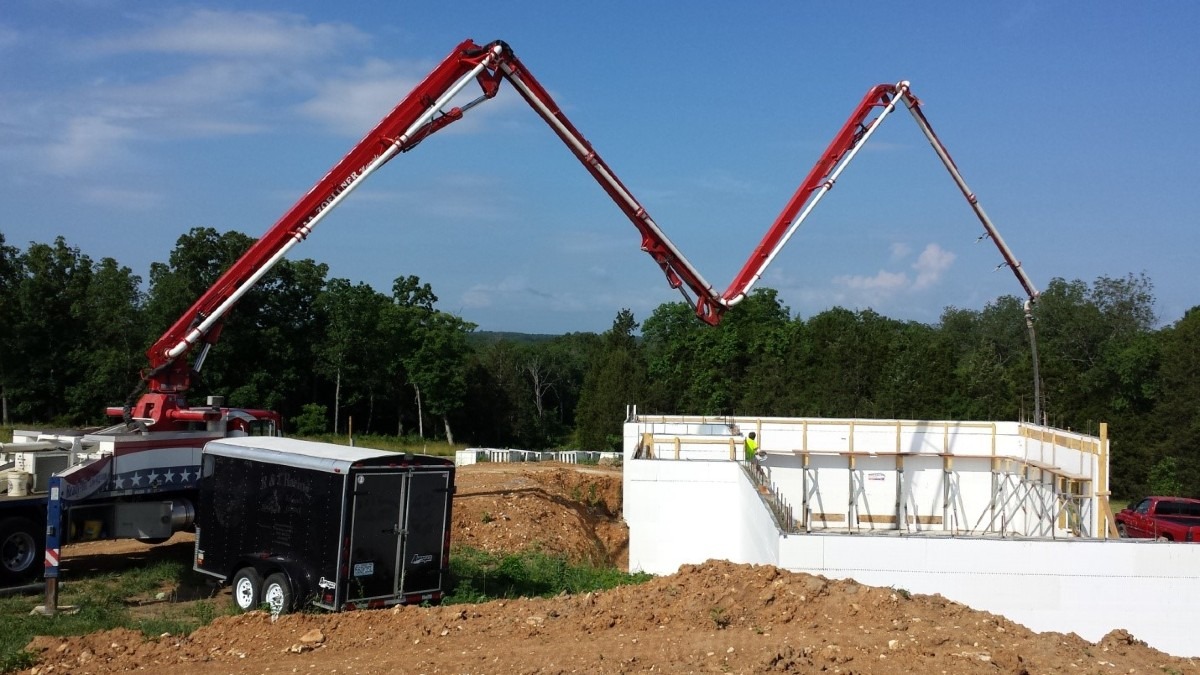
Placing Concrete with a Boom Pump
Using a boom pump to place concrete into ICF forms is by far the most preferred and efficient method. We recommend to use a double “S” bend or double 90° fitting at the discharge point of the pump line. This will help reduce the flow rate of concrete to the desired levels.
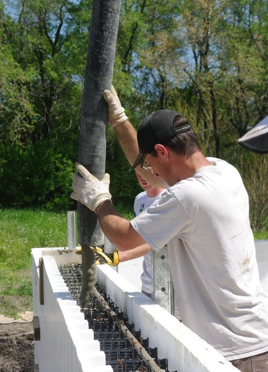
Use a flexible hose of appropriate length for controlling flow rates and safety concerns. Many ICF contractors will also use 3” (76mm), 2.5” (64mm) or 2” (51mm) reducer fittings with a flexible hose. The reducers make it more convenient to pour the concrete into the ICF forms. But they can also have the effect of increasing the pressure and flow rate. With high flow rate the concrete can discharge. The contractor decide which fittings are the most appropriate for a given project. Only they should stay within the recommended rates and do not damage the forms.
Crew Size
On pour day a total crew of 4 is generally a least to work with plus the pump operator. There is a need for three on the scaffold; one person on the hose, and two people on the vibrator. On the ground one or two persons will be filling and blocking window bucks. They will thumping the wall, cleaning slops, untangling the electric cords of the vibrator, etc. Generally we recommend a crew of 5-6.
Pouring the Concrete
Important Notes:
- Remember, concrete should always be poured at a steady rate and in lifts between 3’ to 4’ (0.9 to 1.2m) maximum at a time. Using the recommended pour rate, a typical 9’ (2.7 m) high wall should be poured within a span of 3 hours.
- If using a boom pump, it is important to have the operator dump the “pump prime” (sludge that initially comes out of the hose) outside of the forms or back into the pump.
Pouring Concrete in 90° Corners
It is advisable to start pouring concrete at a corner and then work your way around the wall perimeter in a circular manner. However, corners require special attention during the pour. Because of their geometry, corner blocks are always subjected to more lateral pressure due to concrete placement than the straight blocks. The key issue is to equalize the concrete pressure on both sides of corner blocks as much as possible.
The following precautions should be followed:
- Start by pouring concrete at approximately a distance of 2-3’ (0.6-0.9m) away from the corner center.
- As you fill up the walls to the required lift height, make sure to pour concrete at approximately the same rate on both sides of the corner block by moving the pump hose or discharge point in a back and forth rhythm.
- DO NOT allow concrete to accumulate on one side of a corner block at any time. This may cause a blowout during the concrete pour.
- You should not pour concrete for a subsequent lift in and around the same corner block until at least an hour has passed.
- Ensure proper concrete consolidation
Pouring Concrete around Windows/ Doors & Straight Sections
- Typically, contractors will start by bringing the boom hose down and filling the bottom of the window bucks first. Each window bottom should be consolidated using a concrete vibrator and then screeded off. a. Depending on the slump, it is advisable to nail or screw an OSB cap over the opening(s) in the bottom of the window buck, to prevent the concrete from bulging up or overflowing when you pour down the sides from above in the next passes.
- Window and door bucks should not be filled on one side at one time. Fill both sides of the opening using a back-and-forth rhythm and avoid spilling concrete into the window and door headers (also known as lintels) in doing so. a. With a 2-3” (51 -76 mm) reducer on the pump hose, it is frequently possible to hold back the flow of concrete briefly by placing one’s rubber-gloved hand over the end of the nozzle and quickly swinging the hose to the other side of the window or door.
- Pour concrete normally into straight sections up to the required lift height.
- As the walls are filled with a lintel, ensure a continuous pour along its length without creating any cold joints. Proper and adequate concrete consolidation in lintels is of paramount concern.
- Stop short of pouring concrete into a second corner by approximately 2-3’ (0.6-0.9m). Follow the recommendations given above for concrete placement in corner blocks.
Concrete Consolidation
What is Consolidation
Consolidation is the process of compacting freshly poured concrete. Concrete MUST be consolidated to:
- Eliminate stone pockets, honey-comb, and entrapped air
- Mold concrete within the forms and around embedded items
- Ensure reinforcing steel is properly embedded and bonded to the concrete paste
Methods of Concrete Consolidation
The concrete industry has accepted two types of concrete consolidation, internal and external.
Internal Consolidation
Internal consolidation can be further divided into two types:
- Mechanically using proper size immersion type concrete vibrator (also known as poker or spud vibrators). This is the most preferred method for adequate consolidation.
- Manually using steel rods and “rodding” the concrete. This is not a practical method for use with ICF and does not provide adequate consolidation of the concrete. Engineers highly recommend using a proper size concrete vibrator for adequate concrete consolidation. Using hand rodding to consolidate concrete in ICF walls should be AVOIDED.
External Consolidation
This method involves attaching a mechanical vibrating device to the outside of the ICF forms. Although this method may be acceptable, experience has shown it is not as effective as internal mechanical vibration. External vibration methods such as manually tapping on the outside of the forms are NOT ACCEPTED as an adequate means of consolidating concrete in ICF and must be AVOIDED.
Using Concrete Vibrators
Recommended Specifications
Vibrators consist of a vibrating head connected to a driving motor by a flexible shaft. Inside the head, an unbalanced weight connected to the shaft rotates at high speed, causing the head to revolve in a circular orbit. The motor can be powered by electricity or gasoline. The vibrating head is usually cylindrical with a diameter ranging from ¾-7” (19-178mm). The dimensions of the vibrator head, as well as its frequency and amplitude in conjunction with the workability of the mixture, affect the performance of a vibrator.
| Specification | 4 and 6” (102 and 152mm) ICF | 8, 10 & 12” (203, 254 and 305mm) ICF |
| Maximum vibrator head diameter | 1” (25mm) | 1.25” (32mm) |
| Frequency (vibrations per minute) | 10,000 pm | 9,000 vpm |
| Minimum Radius of Action | 4” (102mm) | 6” (152mm) |
| Insertion on center spacing | 6” (152mm) | 9” (229mm) |
| Centrifugal Force | 220 lbs (100 Kg) | 500 lbs (227 Kg) |
| Compaction rate | 2-4 yds3 /hr (1.5-3 m3 /hr) | 2-5 yds3 /hr (1.5-3.8 m3 /hr) |
Guidelines for Concrete Consolidation: Recommended Practices

- Consolidation MUST be done immediately after fresh concrete is poured and before it sets.
- Completely immerse vibrator head in concrete during consolidation.
- Insert vibrator vertically and let it sink as quickly as possible under its own weight to the desired depth.
- Hold the vibrator 5 to 15 seconds then slowly lift up, approximately 3”/sec (76mm/sec) staying behind the trapped air’s upward movement.
- Move vibrator and re-insert at a distance 1.5 times the radius of action as shown in diagram below. Figure 14 – Vibrator head placement Figure 4 – Radius of action of concrete vibrator Figure 16 – Insert vibrator head at 1.5 times radius of action
- Allow vibrator to penetrate 6” (152mm) into the previous layer to ensure proper bond and eliminate cold joints.
- Pour concrete into the walls in lifts of 3-4’ (0.9-1.2m) high per hour. For proper consolidation, each of the lifts should be poured in layers of the same thickness as the vibrator head length minus depth of penetration into previous layer, typically 6” (152mm).
- Stop vibration when the surface becomes shiny and there are no more breaking air bubbles.
- Ensure the vibrator flexible shaft has enough length to match the wall height being poured.
- Make sure there are enough workers for placing and consolidating concrete during the pour. A two-man crew should be handling the concrete vibrator and follow immediately after the person working the pump hose as each layer is poured.
Practices to Avoid:
- Do not use vibrator to move concrete laterally. This causes segregation.
- The vibrator head should not touch the sides of the ICF forms. It should only be in contact with concrete.
- Do not immerse the vibrator head down the same path more than once.
- Do not run the vibrator in air for more than 15 seconds. This will cause overheating.
- Avoid sticking the vibrator head into the top of a concrete heap. To flatten a concrete heap, insert the head around the perimeter. Do this carefully to avoid segregation.
Finishing the Concrete Pour
If a second floor will be constructed, stop filling the top course of block at least 2” (51mm) below the block top. Vibrate it thoroughly but leave it rough so that the next pour will have a good mechanical bonding surface. An excellent bond will develop by leaving the concrete unfinished. If this is the final course of block that will be poured, then the concrete should be troweled down smoothly, (recommend the use of a laser level at this point) and anchor bolts should be put into the wet concrete after finishing. We recommend wet setting the anchor bolts into the screeded top of the wall and install the mudsill after the concrete has set.
Mudsills or top plates can either be installed to be full width and extend all of the way to the surface of the blocks or it can be recessed within the block cavity so that the EPS foam extends unbroken to the rafters. It gets very busy at the end of the pour, the anchor bolts locations be marked on the sides of the block before the pour, and the anchor bolts be distributed onto the scaffolding near where they will be placed.
After the Pour: Recheck Wall Straightness and Adjust
After pouring is complete, immediately check the corners again for plumb and the wall for straightness. You have a short window in which the bracing system can push and move the wall. If realignment is required adjust the bracing to do so. It is good to have 3 to 4 spare braces ready in the event you need to quickly install an additional adjustable brace to push the wall in an area that you didn’t expect.
Preparing a Blowout Kit
Before the pour, make up a kit to respond to blowouts that has the following:
- A few pieces of OSB or plywood, 24x24” (610x610 mm) or so.
- A container of drywall screws
- A fully charged electric driver drill
- A portable ladder sufficient to reach whatever height is involved on the side of the wall away from the scaffolding.
Before all pours, brief everyone on the crew on procedures to handle a blowout.
If a blowout occurs, the ground man should:
- Waive off the pump and vibrator
- If the foam has only bulged and not separated from the webs, install a piece of form support at the same location. You can use an extra bracing for that purpose.
- If foam has broken out, remove it and clean out concrete, reinsert the broken piece of foam so that it is flush with the wall
- Install one or more pieces of OSB with multiple screws into intact webs or bucks on either side of the failure location
- Go back to work as normal, a very minor event if you are prepared