 EPLAN.HOUSE
TRUSS AND ROOF TERMINOLOGY
APEX: The highest point on a truss where the sloping top chords meet (Figures 3, 4 & 6).
AXIAL FORCE: A push (compression) or pull (tension) acting along the length of a member. Usually measured in Newtons (N) or kiloNewtons (kN).
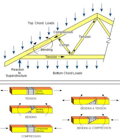
AXIAL STRESS: The axial force acting at a point along the length of a member, divided by the cross-sectional area of the member. Usually measured in MegaPascals (MPa) or Newtons per square millimeter (N/mm2 ). (Figure above)
BARGE BOARDS: Trim boards applied to gable ends of buildings. (Figure 2 & 10) BATTENS: Small-section timber members – usually 36x36 (1,5 inches) spanning between trusses, connected to the top of the top chord of the truss, and usually supporting a roof covering of tiles or slates (Figure 4).
BATTEN CENTRES: The distance between centre lines of battens, measured along the slope of the top chord (Figure 8).
BAY LENGTH: Also called PANEL LENGTH. In a truss, this refers to the horizontal distance between the centres of joints or nodes in either the top or bottom chord. In a roof, it refers to the space between trusses, e.g. a single or double truss spacing where bracing occurs. (Figure 7 & 8)
BRACED BAY: The space between 2 or more trusses in a roof section where bracing is positioned (Figure 2) BEAM: A solid or composite timber lintel that usually supports trusses or rafters. (Figure 11)
BEAM POCKET: A void deliberately set into a wall to allow a beam, truss horn, or floor truss to bear on the wall. (Figure 11 & 21)
BEARING: Structural support of trusses. This is usually a wall with a timber wall plate, but maybe a cleat or hanger connected to a girder truss, a beam, or a wall (Figures 3 & 4). BEARING CUT or SEAT CUT: (See Seat Cut)
BEARING WIDTH: The horizontal width of the structural support of trusses – usually the timber wall plate (Figures 5, 7 & 8).
BENDING MOMENT: A measure of the bending effect on a member due to forces acting perpendicular to the length of the member. The bending moment at a given point along a member equals the algebraic sum of all perpendicular forces, either to the left or right of the point, multiplied by their corresponding distances from the point. Usually measured in Newton millimeters (N.mm) or kilonewton meters (kN.m). (Figure 18)
BENDING STRESS: The force per square millimeter of area acting axially at a point along the length of a member, resulting from a bending moment applied at that point. Usually measured in Newtons per square millimeter (N/mm2 ) or MegaPascals (MPa). (Figure 18)
BINDER: (See Runner)
BOTTOM CHORD (BC) or TIE BEAM: Horizontal or sloping member that establishes the lower edge of a truss and usually carries combined bending and tension stresses (Figures 3 - 6).
BOTTOM CHORD PITCH: The angle of a sloping bottom chord (BC) or tie beam relative to the horizontal (Figure 8).
BRACING: Timber members placed perpendicular or diagonally between trusses to prevent movement due to lateral forces (such as wind) or buckling forces due to compression. Rules for bracing are given in SANS 10243: “The Manufacture and Erection of Timber Roof Trusses”, and in the “Roof Erectors Handbook”, volumes one and two, published by the Institute for Timber Construction. (Figure 2)
BRANDERING: Small timber sections – usually 36x36 connected to the underside of the bottom chord and used to support a fixed ceiling (Figure 3).
BUCKLING: Out-of-plane bending, bends / buckles around the thinnest or weakest part of the structural member, e.g. a web that is subjected to an excessive amount of compression in relation to its length to breadth ratio. (Figure 20)
BUTT CUT: A slight vertical cut (usually less than 75mm) at the outside edge of a truss’s bottom chord
to ensure the correct height over the wall plate (Figures 5b & 7).
CAMBER: An upward vertical displacement built into a truss to compensate for deflection. (Figure 17)
CANTILEVER: The part of a structure that extends outside of its outer supports, measured from the
outer edge of the wall plate to the end of the bottom chord. (Figure 4).
CANTILEVER STRUT: A web that joins the bottom chord above the cantilever bearing point to the top
chord of a cantilevered truss (Figure 4).
CEILING: A Sheeted surface that separates the internal void in the roof with the livable area below the
roof. (Figure 3)
CHORD: One of the main members (Top Chord or Bottom Chord) that form the outline of the truss and
that are subject to relatively large axial forces and bending moments. (Figure 3 & 9)
CLEAR SPAN: The horizontal distance between interior edges of supports (Figures 3 - 9).
COMPRESSION MEMBER: A structural member that has purely axial compressive forces in the
the direction of the grain – forces that shorten or compress the member. (Figure 18)
CONCENTRATED LOAD: A load applied at a given point over a maximum of a 100 x 100mm area, e.g.
chandeliers, man loads, air conditioners, geysers, internal gutters, etc. (Figure 19)
DEAD LOAD: Any permanent load applied to a truss such as metal roof sheeting, concrete tiles,
gypsum ceiling board, purlins, battens and the self-weight of the truss, etc. (Figure 3)
DEFLECTION: Downward vertical movement of a truss – in the plane of the truss – due to dead & live
loads applied to it. (Figure 19)
DESIGN SPAN or NOMINAL SPAN: The horizontal distance between the outside edges of the
supports or to the centre of interior support (usually wall plates). This is the span dimension
used in the design, and in a standard truss, it is normally the tie beam length (Figures 3 - 9).
EAVES: The part of a building that meets or overhangs the exterior load-bearing walls. (Figure 2)
EFFECTIVE LENGTH: The distance between two adjacent points of zero bending moment due to
buckling, these being two points between which the deflected member would be in single
curvature. (Figure 7).
ELEVATION DRAWING: A side view of a building. North, South, East, or West Elevations (see chapter
3 page 3.3 & 3.4).
ENGINEERING DRAWINGS: Drawings that are checked, approved, and signed by a Professional
Engineer (Pr. Eng) or ( Pr. Tech Eng), as required by the Professional Engineers’ Act.
FASCIA: Trim board connected to the ends of overhangs at the eaves of buildings. (Figure 3)
FLYING RAFTER: A mono-pitched Jack truss whose top chord extends over the horizontal top chord of
a truncated girder and the truncated trusses in a hip construction (see page 3.13).
FLYING VALLEY: A Valley junction in which the end of a wider roof section extends onto a narrower
roof section (see page 3.16).
GABLE LADDER: A ladder-like structure placed over a gable wall to support the gable overhang of a
roof. (ITC Roof Erector’s Handbook Volume 2 Revised Edition 2010/11 – Detail ref: Gable- Pg 33)
GABLE WALL: The vertical wall at the end of a pitched roof. The wall extends to the underside of the
roof covering (Figure 1).
GEYSER PLATFORM: A platform supported on the bottom chords of two or more trusses designed to
carry a geyser. (ITC Roof Erector’s Handbook Volume 2 Revised Edition 2010/11 – Detail ref:
Geyser 2- Pg 31. For Solar Geysers pages 90, 91 & 92)
GIRDER TRUSS: A truss that supports other trusses, beams, or rafters (Figures 1 & 2).
GUTTER: A sheet metal or PVC profile attached at the end of the overhang of the roof trusses to catch
rainwater runoff from the roof (Figure 3)
HEEL: The part of a truss where the top chord and bottom chord intersect (Figures 3 - 6).
HEEL HEIGHT: The vertical height from the bottom of the bottom chord to the top of the top chord
above the heel line at the outside edge of the bearing (Figures 5, 7 & 8).
HEEL LINE: The vertical line at the outside edge of the bearing (usually the wall plate) (Fig 5, 7 & 8).
HIP: The end of a roof section with a sloping end plane (Figures 1 & 2).
HIP LINE: The diagonal line formed by the intersection of two downward sloping planes. (see Figure 1).
INTERIOR BEARING TRUSS: Truss with structural support at its centre. (Figure 9)
JACK TRUSSES: Small mono-pitch trusses in a hip construction (Figure 1 & 2).
JOINT or NODE-POINT: Point of intersection of two or more members of a truss (Figures 4 & 5).
KING POST: The vertical web at the centre of a truss ( Figure 3)
LAST BATTEN: (See Tilt Fillet)
LATERAL BRACE: Members placed and connected at right angles to top chords (Purlins or battens) or
bottom chords (Bottom chord runners) or webs (Web runners) of a truss, which, in conjunction
with cross-bracing, form rigid triangles that prevent lateral movement. (Figure 3)
LIVE / VARIABLE LOAD: Non-permanent or temporary loads that have a reasonable probability of
being applied to a structure at some time, for a period less than 3 months, but in most cases less
than 24 hours, such as construction or maintenance workers, wind, rain, hail or snow. (Figure 21)
LOAD BEARING or SUPPORTING WALLS: The exterior walls of a building in most cases are load-bearing. Interior walls can also be load-bearing. Load-bearing brick walls are normally two bricks
thick and have a foundation under them. Sometimes the floor slab is thickening under interior load-bearing walls to accommodate for the extra load. If it is not clear on a drawing if an interior walls is
load-bearing, it is advisable to contact the structural engineer to confirm if you can use it as a
bearing wall. Wall plates are normally placed on top of load-bearing walls. (Figures 3, 4 & 9).
MONO-PITCH TRUSS: A truss that has only one sloping top chord, with a vertical web on the other
side. (Figure 13)
MONOPLANAR TRUSS: A truss with all chords and webs assembled in a single plane (as is the case
with pre-manufactured nail-plated trusses). (Figure 3, 4, 9, 10, 11 & 13)
NAIL PLATE: A galvanized steel plate punched to form a nail pattern integral with the plate. These are
used to connect the timber members of the truss in the same plane (Figures 3 & 4).
NODE / NODE-POINT or JOINT: (See Joint)
NOMINAL SPAN: This refers to the Design Span. (Figure 3, 4, 5, 7, 8 & 9)
NON-LOAD BEARING WALLS: These walls are usually interior walls in a building that are not
designed to carry any loads from the roof or floor. (Figure 9)
OVERALL (O/A) HEIGHT: The vertical height from the bottom of the bottom chord to the top of the top chord (usually the apex) (Figures 7 & 8)
OVERHANG (O/H): The extension of the top chord of a truss beyond the support (Figures 3 - 9).
OVERHANG LENGTH: The horizontal length of the extension of the top chord beyond the outside edge
of the bearing support (Figures 7 & 8).
OVERLAY ROOF: The roof section which, at a T-Junction is extended onto the UNDERLAY ROOF with
a valley (Figure 2, see page 3.16).
PANEL: A truss segment defined by two adjacent joints or nodes. (Figure 7 & 8)
PANEL LENGTH: (See Bay lengths).
PARAPET WALL: The vertical wall at the end of a building section, extending above the roof covering
(Figures 1, 2 & 21).
PEAK: (See Apex)
PIGGY-BACK TRUSS: A truss that is split horizontally, usually because of transportation
considerations, with a standard or valley truss resting on top of a truncated truss (Figure 6).
PLUMB CUT: A vertical cut to the end of the top chord to provide for vertical (plumb) installation of the
fascia or gutter (Figure 3).
PURLINS: Horizontal timber members spanning between trusses, connected to the top of the top
chords, and usually supporting a roof covering of sheeting (Figures 3, 7, 10, 12, etc).
PURLIN CENTRES: The distance between centre lines of purlins, measured along the slope of the top
chord (Figure 7).
PURLIN SPACING / PURLIN CENTRES: Space between the centre lines of adjacent purlins (Figure 7).
RAFTER: A sloping beam that supports a roof cover, or the sloping Top Chord (TC) of a truss. (Figure
3, 4 & 12)
RAKED LENGTH: Lengths measured on the slope, e.g. raked Top Chord lengths (Figure 8).
REACTION: The force at a support point of a truss that is equal but opposite to the sum of the dead and live loads being transferred to that point. (Figure 18)
REGISTERED PERSON: A person who is registered with the Engineering Council of South Africa.
RESPONSIBLE PERSON: A competent person who takes responsibility for designing, erecting,
manufacturing, or inspecting a roof structure.
RIDGE: (See Apex)
RIDGE CAP: A preformed metal profile that is used to seal off the ridge in a metal sheeted roof (Figure
3)
RIDGELINE: A line formed at the top of a roof by the intersection of two sloping planes (Fig 1 & 2).
ROOF COVERING: The roofing material – sheeting, tiles, or slates – is placed on top of the timber roof
structure. (Figure 10 & 12)
ROOF PITCH / SLOPE: The angle of a roof plane relative to the horizontal. (Figure 7, 8 & 9)
ROOF PLAN: A drawing of a roof as viewed from above (Figure 2).
ROOF PLANE: The two-dimensional, usually sloping surface of a roof, extending from the eaves to the
ridgeline between hip, valley, gable, or parapet lines (See Chapter 3 Pages 3.3 thru 3.8).
ROOF SPAN: The distance between supporting walls, usually measured parallel to the truss. (Figure 9)
RUNNER or BINDER: Continuous bracing member that runs the length of the roof to provide lateral
stability for web members or chords of trusses in conjunction with triangulated cross-bracing. They
reduce the effective length of a member. (Figure 3, 4 & 6)
SCALE: The ratio of the drawing size to the actual size of the entity drawn (see page 5.7).
SCALE DRAWING: A drawing in which the actual size of the entity drawn is reduced in a fixed ratio,
thus maintaining the proportions of the entity drawn (see page 5.7).
SCARF: The part of the heel of a truss where the underside of the top chord abuts the sloping cut to the
top of the bottom chord (Figure 5).
SCARF CUT LENGTH: The length of the sloping cut to the top of the bottom chord where it abuts the
the underside of the top chord (Figure 5).
SCARF LENGTH: The length, measured horizontally, of the scarf cut (Figure 5).
SCISSOR TRUSS: A truss with sloping or pitched bottom chords (Figure 8).
SEAT CUT or BEARING CUT: The horizontal cut to the lower end of a sloping or pitched bottom chord,
usually matching the wall plate width, to provide a stable bearing (Figure 8).
SECTION DRAWING: A drawing showing a vertical 'slice' through a building (see page 3.9).
SELF-WEIGHT LOAD: The load that consists of the weight of all the members and nail plates of the
structure itself. (Figure 3)
SHEAR FORCE: The resultant of all forces acting perpendicular to a structural member at a crosssection through the member, acting on either side of the cross-section. (Figure 19)
SHORT-TERM LOADING: Imposed / live loads of short duration, such as wind or hail loads. (Figure 20)
SPAN: When not otherwise specified this refers to the nominal or design span i.e. the horizontal
distance between the outside edges of the supports or bearings – in a standard truss this is
usually the bottom chord or tie beam length. (Figure 3 – 9)
SPAN EXTENSION: An extension to the bottom chord at the heel to ensure the correct height over the
wall plate (Figure 5c).
SPLICE POINT: The point at which two chord members are joined together to form a single member.
(Figure 3 & 7)
SPLIT TRUSS: A truss that is intersected by a chimney or similar vertical obstruction. (Figure 13)
SQUARE CUT: A square cut to the end of the top chord, i.e. perpendicular to the edges of the chord
(Figure 4).
STUB END: The end of a truss that is trimmed back so that the top and bottom chords do not meet at a
heel but are separated by a vertical member (Figure 4).
STUB HEIGHT: The vertical height from the bottom of the bottom chord to the top of the top chord
measured at the outside edge of the bearing width (Figure 7).
STUB POST: The vertical web at the stubbed end of a truss (Figure 4)..
SUPPORT: A wall, post, beam, or girder on which a truss is supported. (Figure 7, 8, 9 & 11)
SUPPORT POINT: The point on a support that is used to define the design span. At end support it is
at the outside edge of the support or bearing width, i.e. on the heel line (Figures 7 & 8); and at
internal support, it is usually on the centre-line of the bearing width. (Figure 9)
SYMMETRICAL TRUSS: A truss with the same dimensions and configuration of members on each side
of the truss' vertical centre line (Figures 3, 6 & 8).
TENSION MEMBER: A structural member that has purely axial tensile forces in the direction of the
grain – forces that stretch or elongate the member. (Figure 18)
TIE BEAM / BOTTOM CHORD: (See Bottom Chord).
TILT FILLET / TILTING FILLET (LAST BATTEN): The last batten at the end of the overhang which is
of a wider section timber (38x50) in order to raise the lowest row of tiles to a similar slope line as
the other tiles (Figure 4).
TOP CHORD / RAFTER: The sloping or horizontal member that establishes the upper edge of a truss
(Figures 3 & 4).
TOP CHORD PITCH: The angle of the top chord or rafter relative to the horizontal. (Figure 7, 8 & 9)
TRADITIONAL TRUSS: A truss that is built with lapped members, connected with bolts and nails.
(Figure 14)
TRIANGULATION: Webs and chords forming triangles to ensure the stability of a structural frame such
as a truss. (Figure 15)
TRIBUTARY AREA: Is the area of a floor or roof that will be carried by a structural member or
component. This area is used to calculate the uniformly distributed live load.
TRUNCATED TRUSS: A truss that is flattened at the top to suit the height requirements dictated by its
position in the roof. A truss may also be so manufactured because of transportation
considerations, e.g. the lower portion of a piggyback truss (Figure 6).
TRUNCATED TRUSS HEIGHT: The height from the bottom edge of the bottom chord to the top edge of the horizontal top chord (Figure 6)
TRUSS: A triangulated combination of members and joints that forms a rigid structural component of a
roof, designed to support both permanent and imposed loads. (Figure 1 – 16)
TRUSS SPACING / TRUSS CENTRES: The distance between the centre-lines of adjacent trusses.
(Figure 11)
TRUSS TYPES: Names given to trusses with different shapes and different web configurations. See
page 2.18 for a list of Truss Types.
UNDERLAY ROOF: The roof section, at a T-Junction, onto which a valley extends (Figure 2)
VALLEY: The part of a pitched roof forming a junction between two perpendicular roof sections (Figure
1 & 2).
VALLEY LINE: The diagonal line formed by the intersection of two planes, sloping upwards from the
intersection (Figure 1 & 2).
VALLEY TRUSS: A truss used to form a valley in association with standard or special trusses (Figures
1 & 6).
VIERENDEEL TRUSS: A truss that lacks triangulation in its frame, in which complete joint stiffness
must be provided. (Figure 15)
VIERENDEEL BAY: A bay in a truss that is not triangulated. (Figure 15)
WALL PLATES: Timber members, usually 38x76 or 38x114 S.A. Pine, laid flat on top of the load-bearing walls (Figures 3 - 16). The roof trusses are placed in their vertical positions on top of the
wall plates, which assist in spreading the roof loading evenly over the brickwork. The wall plates
help to level the top of the brickwork and also lift the trusses up so that overhangs do not clash
with the outside corner of the wall.
WALL TIES: Galvanized steel straps or wire ties that are securely embedded in load-bearing walls at
suitable positions, to anchor roof trusses or rafters to the wall. (Figure 16)
WEB: A member that joins the top and bottom chords of a truss, to form a triangular pattern. Webs may
carry tensile or compressive forces, depending on their position in the truss (Fig. 3 & 4).
Truss types
