EPLAN.HOUSE
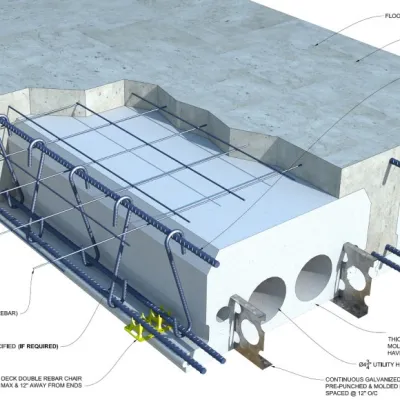
Monolithic reinforced concrete floor slabs, despite a large number of prefabricated slabs, are still in demand. This is especially true if this is a house with a unique layout, where all rooms are of different sizes or crew will make construction without cranes. In such cases, installing a monolithic reinforced concrete floor slab can significantly reduce the cost of materials or delivery and installation. However, more time the builder will spend on preparatory work, including formwork. However, this is not what frightens off people who start concreting the floor. Making the formwork, ordering reinforcement, and concrete is not a problem now. The problem is how to determine which concrete and which reinforcement required for this.
This article is not an action guide but is purely informational. All the subtleties of the calculation of reinforced concrete structures are strictly standardized.
The calculation of any building structure in general and of a reinforced concrete floor slab in particular consists of several stages:
- select the geometric parameters of the cross-section;
- determine the class of concrete and the class of reinforcement so that the projected slab does not collapse when exposed to the maximum possible load.
The calculation we will perform for a section perpendicular to the x-axis.
We will not perform calculations for:
- local compression,
- punching,
- for the action of transverse forces,
- for torsion (limiting states of the first group),
- for opening cracks and deformations (limiting states for the second group).
Assuming in advance that for an ordinary flat suspended floor in a residential house, such calculations are not required, and as a rule, it is. Moreover, we will restrict ourselves only to the calculation of the transverse (typical) section for the action of the bending moment. Those who do not need explanations on the definition of geometric parameters, the design model's choice, the collection of loads, and design prerequisites can go straight to the calculation example.
Stage 1. Determination of the calculated length of the slab.
The actual length of the slab can be anything, but the calculated length, in other words, the beam's span (and in our case, the floor slab), is an entirely different matter. Span is the distance in the light between the load-bearing walls. In other words, this is the length or width of the room, from wall to wall. Therefore, it is pretty simple to determine the span of the floor slab. You need to measure this distance with a ruler or other improvised means. Of course, the actual length of the slab will be longer. A monolithic reinforced concrete floor slab can be supported by load-bearing walls made of brick, cinder block, stone, expanded clay concrete, or aerated concrete blocks, and in our case, this is not important. However, suppose the load-bearing walls are lined with materials that have insufficient strength (foam concrete, aerated concrete, expanded clay concrete, cinder block). In that case, the wall material must also be counted on for appropriate loads. In this example, we will consider a single-span floor slab resting on two load-bearing walls. Calculation of a reinforced concrete slab based on a contour, i.e., on four load-bearing walls, as well as multi-span slabs, is not considered here.
The above does not remain an empty sound and is better assimilated. We take the value of the calculated length of the slab l = 4 m.
Stage 2. Preliminary determination of the geometrical parameters of the slab, the class of reinforcement, and concrete.
We do not know these parameters yet, but we can set them to count something.
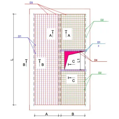
Let us set the height of the slab h = 10 cm, and the conditional width b = 100 cm. In this case, the convention means that we will consider the floor slab as a beam with a height of 10 cm and a width of 100 cm, which means that the results obtained should be applied to all remaining centimeters slab width. If a floor slab with an estimated length of 4 m and a width of 6 m is to be manufactured, then for each of these 6 meters, the parameters determined for one calculated meter should be adopted.
So we take the values of height h = 10 cm, width = 100 cm, concrete class B20, reinforcement class A400
Stage 3. Determination of supports.
Depending on the support span and the material and weight of the load-bearing walls, the floor slab can be considered:
- a hinged, non-cantilever beam,
- or as a hinged cantilever beam,
- or as a beam with rigid pinching on the supports.
Why it is matter is outlined separately. In what follows, we will consider a hinged supported cantilever beam as the most common case.
Stage 4. Determination of the load on the slab.
Beam loads can be very diverse. From the point of view of structural mechanics, everything that lies motionless on the beam, nailed, glued, or suspended from the floor slab is a static and often constant load. Everything that walks, crawls, runs, drives, and even falls on the beam - these are all dynamic loads. As a rule, dynamic loads are temporary. However, in this example, we will not distinguish between temporary (live) and permanent (dead) loads. The load can also be concentrated, evenly distributed, unevenly distributed, and so on. However, we will not delve so much into all possible combinations of loads. For this example, we will restrict ourselves to a uniformly distributed load since such a loading case for floor slabs in residential buildings is the most common. We measure the concentrated load in Pascal (or pound per square foot (psf) for Imperial units) or in Newtons and the distributed load — in N / m.
We will omit the details of collecting loads on the floor slab here. Let us say that usually, floor slabs in residential buildings are calculated for a distributed load q1 = 4 kPa. With a slab height of 10 cm, the slab weight will add to this load about 2,5 kPa, screed and ceramic tiles can add up to 1 kPa. This distributed load takes into account almost all possible combinations of loads on floors in residential buildings. Nevertheless, no one forbids calculating structures for higher loads. However, we will limit ourselves to this value and, just in case, multiply the obtained value of the distributed load by the safety factor γ = 1.2, if suddenly we still missed something:
q = (4 + 2,5 +1) 1.2 = 9 kPa
Since we will calculate a slab's parameters with a width of 100 cm, this distributed load can be considered a linear load that acts on the floor slab along the y-axis and is measured in kN / m.
Stage 5. Determination of the maximum bending moment acting on the transverse (regular) section of the beam.
The maximum bending moment for a cantilever beam on two hinged supports, and in our case, a floor slab resting on a wall, on which a uniformly distributed load acts, will be in the middle of the beam:
Мmax = (q х l2) / 8 (5.1)
Why this is so is described in sufficient detail in another article.
For a span l = 4 m Mmax = (9 x 42) / 8 = 18kN
Stage 6.1 Design assumptions:
Calculation of reinforced concrete elements for ultimate forces is based on the following design assumptions:
- The tensile strength of concrete is assumed to be zero. This assumption is made on the basis that the tensile strength of concrete is much less than the tensile strength of the reinforcement (approximately 100 times). Therefore, cracks form in the reinforced concrete structure's tensioned zone due to the rupture of the concrete, and thus, in the normal section, only reinforcement works in tension (see. picture 1).
- The resistance of concrete to compression is assumed to be uniformly distributed over the compression zone. The resistance of concrete to compression is assumed to be no more than the design resistance Rb.
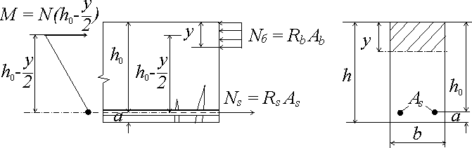
In order to prevent the effect of the formation of a plastic hinge and the possible collapse of the structure, the ratio ξ of the height of the compressed zone of concrete y to the distance from the center of gravity of the reinforcement to the top of the beam h0, ξ = y / ho (6.1), should be no more than the limiting value ξR. The limit value is determined by the following formula:
\[ \xi_R = \frac{0.8}{1+\frac{R_s}{700}} , \text{(6.2)} \]
This empirical formula is based on the experience of designing reinforced concrete structures, where \(R_s \) is the design resistance of reinforcement in MPa. However, at this stage, you can completely do with the table:
| Reinforcement grade | A240 | A300 | A400 | A500 | B500 |
|---|---|---|---|---|---|
| The value of ξR | 0,612 | 0,577 | 0,531 | 0,493 | 0,502 |
| The value of aR | 0,425 | 0,411 | 0,390 | 0,372 | 0,376 |
Note: When performing calculations by non-professional designers, I recommend underestimating the value of the compressed zone ξR by 1.5 times.
where a is the distance from the center of the reinforcement cross-section to the bottom of the beam. This distance is necessary in order to ensure the adhesion of the reinforcement to the concrete; the larger a, the better the reinforcement girth, but at the same time, the useful value of h0 decreases. Usually, the value of a is taken depending on the reinforcement's diameter. In contrast, the distance from the reinforcement bottom to the beam's bottom (in this case, the floor slab) must be at least the diameter of the reinforcement and at least 10 mm. We will make further calculations for a = 2 cm.
- For ξ ≤ ξR and the absence of reinforcement in the compressed zone, the strength of concrete is checked according to the following formula:
\[M \leq r_b b_y (h_0-0,5y) \]
or
\[ M \leq R_b b_y h_0 (1 - \frac{y}{2h_0}) \quad\text {(6.3.2),} \]
or
\[ M \leq R_b b h_0^2a_m, \quad \text {(6.3.3),}\]
where
\[ \text{where } a_m = \frac{y (1 - \frac{y}{2h_0})}{h_0} = \xi (1 - \frac{\xi}{2}) = \xi - \frac{\xi^2}{2} \quad \text {(6.3.4)} \]
The physical meaning of formula (6.3) is clear. Since any moment can be represented as a force acting with a specific shoulder, the above condition must be met for concrete. Other formulas are obtained by the most straightforward mathematical transformations, the purpose of which will become apparent below.
- Checking the strength of rectangular sections with single reinforcement at ξ ≤ ξR is carried out according to the formula:
M ≤RsAs (h0 - 0.5у) (6.4)
According to the calculation, the essence of this formula is as follows: the reinforcement must withstand the same load as concrete since the same force acts on the reinforcement with the same shoulder as on concrete.
Note: this design scheme, assuming the shoulder of the force action (h0 - 0.5у), makes it possible to relatively quickly determine the main parameters of the cross-section, as the following formulas will show, which logically follow from formulas (6.3) and (6.4). However, such a design scheme is not the only one. The calculation can be made relative to the center of gravity of the reduced section. However, unlike wooden and metal beams, it is rather difficult to calculate reinforced concrete based on the ultimate compressive or tensile stresses in the transverse (normal) section of a reinforced concrete beam. Reinforced concrete is a composite, very heterogeneous material, but that is not all. Numerous experimental data indicate that the ultimate strength, yield strength, elastic modulus, and other mechanical characteristics of materials have a very significant scatter. For example, when determining the ultimate compressive concrete strength, the same results are not obtained even when the samples are made from a concrete mixture of the same batch. It is explained by the fact that the concrete strength depends on many factors: the size and quality (including the degree of contamination) of the aggregate, the cement activity, the method of mixture compaction, and various technological factors. Considering the random nature of these factors, we consider the ultimate concrete strength with a random value.
The situation is similar for other building materials, such as wood, brickwork, polymer composite materials. Even for classic structural materials such as steel, aluminum alloys, etc., there is a noticeable random variation in strength characteristics. Various probabilistic characteristics are used to describe random variables, which are determined as a result of statistical analysis of experimental data obtained in the course of mass tests. The simplest of them is the mathematical expectation and the coefficient of variation, otherwise called the variability coefficient. The latter is the ratio of the root-mean-square spread to the mathematical expectation of a random variable. So in the design standards for reinforced concrete structures, the coefficient of heavy concrete variability is taken into account by the coefficient of reliability for concrete.
In this regard, no design scheme will be ideal for reinforced concrete. However, we will not be distracted but return to the design prerequisites for this scheme.
The following formula can determine the height of the concrete compressed zone in the absence of reinforcement in the compressed zone:
\[y=\frac{R_s A_s}{R_b b} \quad \text{(6.5)} \]
- To determine the cross-section of the reinforcement, the coefficient am is first determined:
determination of the reinforcing factor
\[a_m=\frac{M}{R_b b h^2} \quad \text{(6.6)} \]
For am < aR, reinforcement in the compressed zone is not required. The value of aR is determined according to the Table 1.
- If there is no reinforcement in the compression zone, the cross-section of the reinforcement is determined by the following formula:
\[A_s=\frac{R_b b h_0 (1-\sqrt{1-2a_m})}{R_s} \quad \text{(6.7), } \]
where \( y = h_0 (1 - \sqrt{1 - 2a_m}) \) is the result of solving the formula's quadratic equation (6.3.4), thus, formula (6.7) is the result of simple transformations of formula (6.5).
Furthermore, now, if you have not yet drowned in this sea of formulas, let's see what the benefits of these calculated prerequisites and formulas are:
An example of calculating a monolithic reinforced concrete non-cantilever floor slab on hinged supports is a uniformly distributed load act.
Stage 7. Selection of the section of the reinforcement.
Design tensile strength for reinforcement of class A400 according to table 7 Rs = 355 MPa. Design compressive strength for concrete of class B20 according to table 4 Rb = 11.5 MPa. All other parameters and loads for our slab were determined earlier. First, using formula (6.6), we determine the value of the coefficient am:
am = 18 / (1· 0.082 · 11.5 ·1000) = 0.24038
Note: since the moment was determined for us in kN (kg·m) and the cross-section dimensions are also conveniently substituted in meters, the value of the design resistance was also reduced to kPa to comply with the dimension.
This value is less than the limit for this class of reinforcement according to Table 1 (0.24038 <0.39), which means that the reinforcement in the compressed zone is not needed according to the calculation. Then, according to formula (6.8), the required cross-sectional area of the reinforcement:
As = 11500·100·8(1 - √1 - 2·0.24038) / 355000 = 7.241 см2.
Note: in this case, we used the cross-sectional dimensions in centimeters and the calculated resistance values in kPa to simplify the calculation.
Thus, to reinforce one running meter of our floor slab, you can use 5 bars with a diameter of 14 mm spaced by 200 mm. The cross-sectional area of the reinforcement will be 7.69 cm2. It is convenient to select reinforcing steel bars according to table 2:
Table 2. Area of individual reinforcement bars
| Area of individual reinforcement bars (cm2) | ||||||||||||
|---|---|---|---|---|---|---|---|---|---|---|---|---|
| Number of bars | Φ6 | Φ8 | Φ10 | Φ12 | Φ14 | Φ16 | Φ18 | Φ20 | Φ22 | Φ25 | Φ28 | Φ32 |
| 1 | 0.28 | 0.50 | 0.79 | 1.13 | 1.54 | 2.01 | 2.54 | 3.14 | 3.80 | 4.91 | 6.16 | 8.04 |
| 2 | 0.57 | 1.01 | 1.57 | 2.26 | 3.08 | 4.02 | 5.09 | 6.28 | 7.60 | 9.82 | 12.32 | 16.08 |
| 3 | 0.85 | 1.51 | 2.36 | 3.39 | 4.62 | 6.03 | 7.63 | 9.42 | 11.40 | 14.73 | 18.47 | 24.13 |
| 4 | 1.13 | 2.01 | 3.14 | 4.52 | 6.16 | 8.04 | 10.18 | 12.57 | 15.21 | 19.63 | 24.63 | 32.17 |
| 5 | 1.41 | 2.51 | 3.93 | 5.65 | 7.70 | 10.05 | 12.72 | 15.71 | 19.01 | 24.54 | 30.79 | 40.21 |
| 6 | 1.70 | 3.02 | 4.71 | 6.79 | 9.24 | 12.06 | 15.27 | 18.85 | 22.81 | 29.45 | 36.95 | 48.25 |
| 7 | 1.98 | 3.52 | 5.50 | 7.92 | 10.78 | 14.07 | 17.81 | 21.99 | 26.61 | 34.36 | 43.10 | 56.30 |
| 8 | 2.26 | 4.02 | 6.28 | 9.05 | 12.32 | 16.08 | 20.36 | 25.13 | 30.41 | 39.27 | 49.26 | 64.34 |
| 9 | 2.54 | 4.52 | 7.07 | 10.18 | 13.85 | 18.10 | 22.90 | 28.27 | 34.21 | 44.18 | 55.42 | 72.38 |
| 10 | 2.83 | 5.03 | 7.85 | 11.31 | 15.39 | 20.11 | 25.45 | 31.42 | 38.01 | 49.09 | 61.58 | 80.42 |
Also, to reinforce the slab, you can use 7 Ø12 mm bars spaced by 140 mm or 10 Ø10 mm bars spaced by 100 mm.
We check the strength of concrete according to the formula (6.5)
y = 355 · 7.241 / (11,5 ·100) = 2.374 cm
ξ = 2.374 / 8 = 0.29573, this is less than the boundary 0.531, according to formulas (6.1) and Table 1, and less than the recommended 0.531 / 1.5 = 0.354, i.e. meets the requirements.
11500 · 100 cm · 2.374 cm · (8 cm - 0.5 · 2.374 cm)/1000000 = 18.6 kN> M = 18 kN, according to formula (6.3)
355000 · 7.69 cm2 (8 cm - 0.5 · 2.374 cm)/1000000 = 18.6 kN > M = 18 kN, according to formula (6.4)
Thus, we have met all the requirements.
If we increase the concrete class to B25, we will need less reinforcement for B25 Rb = 14.5 MPa.
am = 18 / (1 · 0.082 · 14500) = 0.1940
As = 14.5 MPa · 100 cm · 8 cm (1 - √ (1 - 2 · 0.19) / 355 MPa = 6.95 cm2.
Thus, to reinforce one running meter of our floor slab, you still need to use 5 Ø14 mm bars spaced by 200 mm or continue selecting the section. However, you can not strain too much since this slab, considered a hinged beam, will most likely not pass the calculation for the deflection. Therefore it is better to immediately proceed with the estimates for the limiting deformations of the second group, an example of determining the deflection is given separately. Here I will say that for the slab to meet the requirements for the maximum permissible deflection, the height of the slab will have to be increased to 13-14 cm, and the section of the reinforcement will have to be increased to 4-5 steel bars Ø16 mm diameter.